LQ-RTO熱貯蔵高温焼却装置
Cat:装置
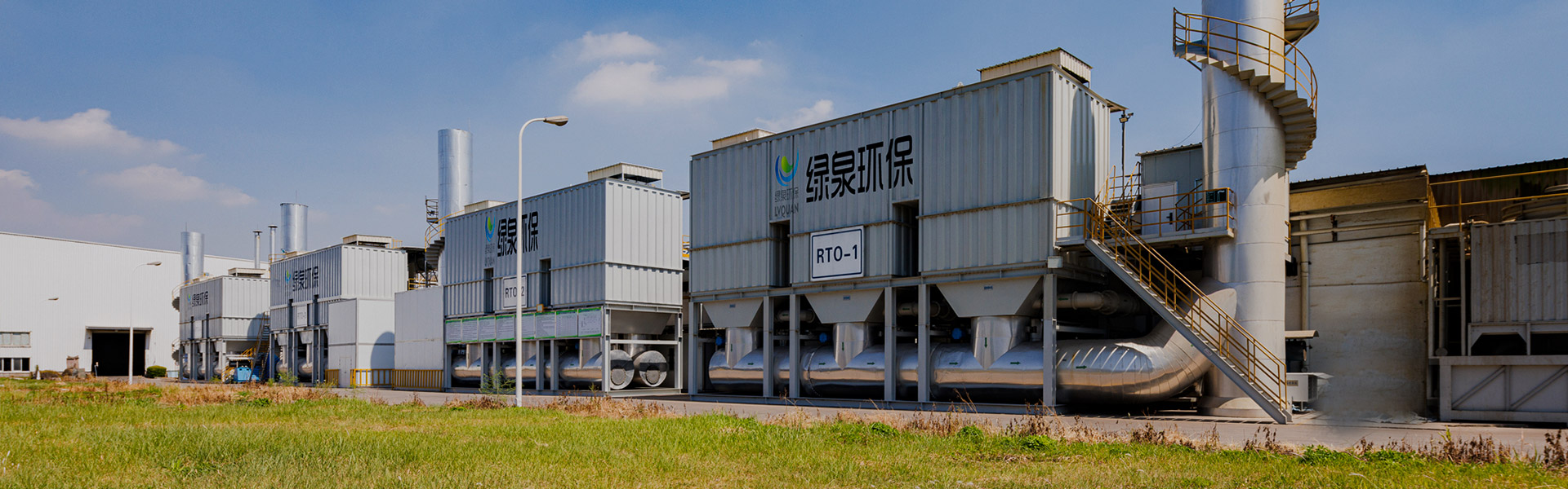
タワータイプRTOの概要 再生熱酸化剤(RTO)は、高温酸化とマルチ塔の熱貯蔵技術を組み合わせた有機廃棄物ガス処理装置です。それは効果的に熱損失を減らし、エネルギーを節約します。
詳細を参照してください火災や爆発のリスクに対する主な防御には、VOC 濃度を爆発下限界 (LEL) の 25% 以下に維持し、自動抑制システムを設置することが含まれます。 VOC 有機廃ガス処理エンジニアリング装置は可燃性の高い化合物を使用して動作するため、本質安全設計は交渉の余地がありません。
最新の治療システムでは複数の保護層が採用されています。 LEL モニターは、濃度 25% でアラームをトリガーし、LEL 50% でシステムを自動的にシャットダウンする必要があります。 熱酸化剤には、入口配管にフレームアレスタと、0.5 ~ 1.0 barg の過圧力に耐える爆発防止パネルが必要です。
| テクノロジー | LEL制限 | 必要な安全装置 |
|---|---|---|
| 再生熱酸化装置 (RTO) | 25%LEL | フレームアレスターバイパスダンパー |
| 触媒酸化剤 | 20%LEL | 温度連動ポイズンガード |
| 活性炭吸着 | 30% LEL | 窒素パージのホットスポット検出 |
| 結露回復 | 制限なし | 防爆電気 (クラス I ディビジョン 1) |
始動前のパージサイクルでは、容器の 4 ~ 6 倍の容積を新鮮な空気と交換する必要があります。 周辺地域の VOC 濃度が 10% LEL を超える場合、火気使用作業の許可が義務付けられます。 すべての導電性機器の静的接地抵抗は 10 オーム未満に保つ必要があります。
捕集効率の低下は通常、フード面の速度が 0.5 m/s 未満であることと、プロセス開口部が密閉されていないために逃散放出が発生することが原因で発生します。 産業評価により次のことが明らかになりました パフォーマンスの低いシステムの 60 ~ 80% 機器の欠陥ではなく、基本的なエアフロー管理の失敗に悩まされています。
キャプチャーフードはメンテナンスが必要です 面速度 0.5 ~ 1.0 m/s 開放水面タンク用と 0.25~0.5m/秒 密閉プロセス向け。ダクト速度が 10 m/s 未満の場合、粒子のドロップアウトが発生します。 15 m/s を超えると過度の圧力損失が発生します。 回転羽根のない 90 度エルボでは、効率が 15 ~ 20% 低下します。
| 問題 | 典型的な影響 | 検出方法 |
|---|---|---|
| フードが発生源から遠すぎる (フード直径の 1.5 倍以上) | 40~60%の損失 | 煙管の可視化 |
| ダクト漏れ(表面積の5%) | 15~25%の損失 | 圧力減衰試験 |
| アンバランスなマルチブランチシステム | 20~35%の損失 | ピトートラバース測定 |
| ファン速度の低下 (10% 削減) | 19% の流量損失 | 振動解析アンプの描画 |
溶剤ベースのコーティング作業では、 ピーク放出スパイク 3 ~ 5 倍の平均負荷 、圧倒的な定速コレクター。圧力トランスデューサーフィードバックを備えた可変周波数ドライブ (VFD) は、負荷変動時に最適な捕捉を維持します。 密閉型コンベヤー システムの捕獲率は 85 ~ 95% であるのに対し、開放浸漬タンクでは 40 ~ 60% です。
適切にメンテナンスされた VOC 処理装置は通常 8 ~ 15 年間使用でき、熱酸化剤は 15 ~ 20 年間使用でき、炭素吸着システムは 3 ~ 5 年ごとに媒体の交換が必要です。 実際の寿命は、耐食性、熱サイクル頻度、予防保守の厳密さに大きく依存します。
RTO のセラミック熱交換媒体は耐久性があります。 10~15年 熱衝撃による劣化の前に、効率が 85% 未満に低下します。直火式酸化剤のステンレス鋼バーナーチューブは長持ちします。 8~12歳 プロセスストリーム中の塩化物含有量に応じて異なります。 ハロゲン化VOCの触媒床は40%早く分解します ケトンやアルコールを扱うものよりも。
| コンポーネント | 標準寿命 | 故障モード |
|---|---|---|
| RTO セラミックメディア | 10~15年 | 熱割れ、目詰まり |
| 触媒(貴金属) | 5~8年 | 中毒、焼結 |
| 活性炭 | 3~5年 | 細孔の飽和、磨耗 |
| 燃焼バーナー | 8~12歳 | 腐食、ノズルの腐食 |
| 換気扇 | 10~15年 | ベアリングの摩耗、インペラの腐食 |
実装する 年に一度の熱画像検査 構造破壊の前に耐火性のホットスポットを特定します。 入口ストリームの pH 緩衝 6.0 未満または 8.0 を超えると、炭素鋼ダクトの寿命が 3 ~ 4 年延長されます。で動作するシステム プレフィルターは微粒子の 95% を除去します 触媒寿命が 30% 長くなります。
適切なサイジングには、処理効率を損なうことなく生産拡大に対応するために、ピーク設計流量を上回る 20 ~ 30% の余剰能力が必要です。 100% の容量で動作する過小なシステムでは、時間の経過とともに自然に発生するフィルターの負荷やダクトの汚れに対処できません。
ハロゲン化VOC(塩化メチレン、パークロロエチレン)の需要 316L ステンレス鋼またはハステロイ C 構造 塩化物応力腐食を防止します。 炭素鋼は 10 倍早く劣化します これらの環境では。ケトンを含むストリームの場合、過酸化物が形成される可能性があるため、アルミニウム成分は禁止されています。
連続パラメータ監視システム (CPMS) 燃焼室温度 (精度 ±5°C)、保持時間、破壊効率を追跡する必要があります。 毎週の校正チェック MACT 標準では四半期ごとの相対精度テスト監査 (RATA) が義務付けられています。
蓄熱式熱酸化剤が達成するもの 95~97%の熱効率 セラミックによる熱回収。ゼオライト媒体を使用した濃縮ホイールは、次のような方法で大量の低濃度ストリームを削減します。 10:1~20:1 酸化する前に燃料使用量を 60 ~ 80% 削減します。
リン、硫黄、重金属は貴金属触媒を毒します。 1ppmという低い濃度でも。シリコーンは活性部位をブロックするシリカ堆積物を形成します。 0.3ミクロンまでの前濾過 活性炭ガードベッドにより触媒の寿命が 2 ~ 3 年延長されます。
活性炭は依然として費用対効果が高い 溶剤回収用途 ここで、吸着剤の再販価値は (> 2 ドル/kg)、入口濃度は 1,000 ppm 未満です。 蒸気再生のコストは炭素 1 ポンドあたり 0.08 ~ 0.12 ドルです 熱酸化燃料コストは 0.15 ~ 0.25 ドルです。
パージサイクルは 3 回の空気交換を達成する必要があります VOC を含むストリームを導入する前に。 RTO は 補助燃料バーナー 30 分以内に設定値 760°C に到達します。バイパス ダンパーは、通常の始動ではなく、異常状態のときにのみ未浄化ガスを迂回させます。

タワータイプRTOの概要 再生熱酸化剤(RTO)は、高温酸化とマルチ塔の熱貯蔵技術を組み合わせた有機廃棄物ガス処理装置です。それは効果的に熱損失を減らし、エネルギーを節約します。
詳細を参照してください
概要 触媒燃焼は、触媒を使用して低温で排気ガスの可燃性物質を酸化して分解する精製方法です。したがって、触媒燃焼は触媒化学変換としても知られています。触媒は酸化と分解のプロセスを加速するため、炭化水素は250〜300℃の温度で触媒によって完全に酸化することができます。 ...
詳細を参照してください
概要 熱貯蔵触媒酸化(再生触媒酸化剤/RCO)は、低温触媒酸化と熱貯蔵技術を組み合わせた有機廃棄物ガス処理装置です。この機器は、浄化後に放電ガスの温度を大幅に低下させながら、熱損失とエネルギー消費を効果的に削減します。
詳細を参照してください")
可変枠ゼオライトターンテーブルの概要 当社のゼオライト濃度ターンテーブルは、ゼオライトモジュールの組み合わせを使用しており、ゼオライト含有量が高い、吸着率が高い、吸着速度が高くなっています。独自の技術によって処理され、脱着中に熱耐性を高め、より徹底的に脱着します。特別な構造によ...
詳細を参照してください
概要 固形廃棄物の焼却炉は、高温燃焼を通じて廃棄物とガスに廃棄物に変換するように設計された固形廃棄物の管理に不可欠な装置であり、それにより環境を浄化します。これらの炉は、給餌システム、燃焼システム、熱回収システム、煙道ガス浄化システム、灰除去システムなど、いくつかの主要...
詳細を参照してください
活性炭繊維有機溶媒浄化回収装置の概要 活性炭繊維有機溶媒溶媒浄化回収システム(ACF)は、吸着剤培地として高品質の活性炭繊維を利用する環境保護装置です。マイクロコンピューターによって制御され、完全に自動化されたこのシステムは、振動の削減、音響断熱、爆発保護、過熱および過...
詳細を参照してください")
VOC-CFT-CO吸着触媒精製装置 固定床ハニカム活性炭と触媒燃焼で構成されるVOC-CFT-CO吸着触媒精製装置は、有機ガス治療の経験20年近くの経験に基づいて当社が開発した新しいタイプの効率的で省エネ環境保護装置です。 LTは二次汚染から解放されており、多くのユーザーによ...
詳細を参照してください")
一連の機器としての固定ベッドゼオライト触媒燃焼の概念 固定床ゼオライト触媒燃焼装置は、低濃度、断続的な生産(造船業など)、およびUV塗料やスチレンなどの揮発性有機化合物の濃度と吸着処理に適しています。継続的な安定した操作、治療空気量、治療廃棄物ガス濃度、排出濃度において独自の利...
詳細を参照してください
目的 主に高温煙道ガスの比例換気に使用されます。 LTは、RTOやその他の高温煙の直接排出場所など、漏れレートの要件が高くない場所で広く使用されています。主に蝶のバルブ本体と一致する空気圧アクチュエータ(GT/RT/AT/AWシリーズ)で構成されており、低圧パイプライン培地のス...
詳細を参照してください
概要 ウェットダスト除去の原理は、ガス液体の2相に完全に接触することにより、気相でダスト粒子を捕獲および分離するプロセスを使用します。 現在、一般的に使用される構造形式は次のとおりです。 1. 水貯蔵:一定量の水が設置され、高速粉塵を含むガスがヒットして...
詳細を参照してください携帯


Copyright © LV Quan Environmental Protection Engineering Technology Co.、Ltd。 All Rights Reserved. VOCS有機廃棄物ガス処理工学機器メーカー

